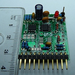
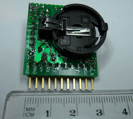
This simple board has been developed to work together with an arduino board, but it can be used in conjunction with every other boards with an I2C bus and a power suplly into the range [2.7..5]V.
The schemathic for this board is shown in the following picture:
In the following table you'll find the complete BOM (Bill Of Materials):
| Part | Value | Device | Package | Library | Sheet |
| BAT | BATTERY20PTH | BATTCOM_20MM_PTH | SparkFun | 1 | |
| C1 | 12p | C-EU025-025X050 | C025-025X050 | rcl | 1 |
| C2 | 12p | C-EU025-025X050 | C025-025X050 | rcl | 1 |
| C3 | 100nF | C-EU025-025X050 | C025-025X050 | rcl | 1 |
| C4 | 10µF | CPOL-EUE2.5-6 | E2,5-6 | rcl | 1 |
| C5 | 100nF | C-EU025-025X050 | C025-025X050 | rcl | 1 |
| C6 | 100p | C-EU025-024X044 | C025-024X044 | rcl | 1 |
| D1 | DIODE-D-5 | D-5 | diode | 1 | |
| D2 | 5.1v | ZENER-DIODEZD-5 | ZDIO-5 | diode | 1 |
| D3 | DIODE-D-2.5 | D-2.5 | diode | 1 | |
| IC1 | RTC | DS1307SO8 | SO08 | SparkFun | 1 |
| IC2 | TEMP | MCP98011 | SO-08 | microchip_n | 1 |
| ICSP | PINHD-1X51X05_C | 1X05_C | pinhead | 1 | |
| JP1 | PINHD-1X71X07_C | 1X07_C | pinhead | 1 | |
| JP2 | PINHD-1X21X02_C | 1X02_C | pinhead | 1 | |
| JP3 | PINHD-1X21X02_C | 1X02_C | pinhead | 1 | |
| L1 | LED3MM | LED3MM | led | 1 | |
| Q1 | 32.768k | CRYSTALTC26H | TC26H | crystal | 1 |
| R1 | 1k | R-EU_0204/2V | 0204V | rcl | 1 |
| R2 | 10k | R-EU_0204/5 | 0204/5 | rcl | 1 |
| R3 | 4.7k | R-EU_0204/2V | 0204V | rcl | 1 |
| R4 | 4.7k | R-EU_0204/5 | 0204/5 | rcl | 1 |
| R5 | 3.3k | R-EU_0204/2V | 0204V | rcl | 1 |
| R6 | 10k | R-EU_0204/5 | 0204/5 | rcl | 1 |
| R7 | 10 | R-EU_0204/5 | 0204/5 | rcl | 1 |
| R8 | 10k | R-EU_0204/5 | 0204/5 | rcl | 1 |
| R9 | 3.3k | R-EU_0204/5 | 0204/5 | rcl | 1 |
| R10 | 3.3k | R-EU_0204/5 | 0204/5 | rcl | 1 |
| R11 | 3.3k | R-EU_0204/5 | 0204/5 | rcl | 1 |
| T | PINHD-1X1 | 1X01 | pinhead | 1 |
The board takes the power supply linking the positive pin of the power supply (Max 5V) with the pin 1 (Vcc) of the pinheader Jp1, while the ground of the power supply shall be connected to the pin 1 (Gnd) of the pinheader Jp1.
Tcn75 Sensor
Resistors R9,..,R11 are used to setup the tcn75 address on the I2C bus to 1. The solderpads set up the sensor address to 0.
The board is configured to have address value 7 on the I2C bus ( 0b10011 111 ).
If you want to change the address you shall unsolder one or more resistors and the link them to GND trough the solder pads A0 A0 A1 A2 as shown in the following table:
| Tcn75 address on the I2C bus | PIN A2 | PIN A1 | PIN A0 |
| 0 | 0 | 0 | 0 |
| 1 | 0 | 0 | 1 |
| 2 | 0 | 1 | 0 |
| 3 | 0 | 1 | 1 |
| 4 | 1 | 0 | 0 |
| 5 | 1 | 0 | 1 |
| 6 | 1 | 1 | 0 |
| 7 | 1 | 1 | 1 |
The alarm pin of the sensor is accessible on the pin2 of the pin header Jp2.
In the following picture you can see the top view of the board:


