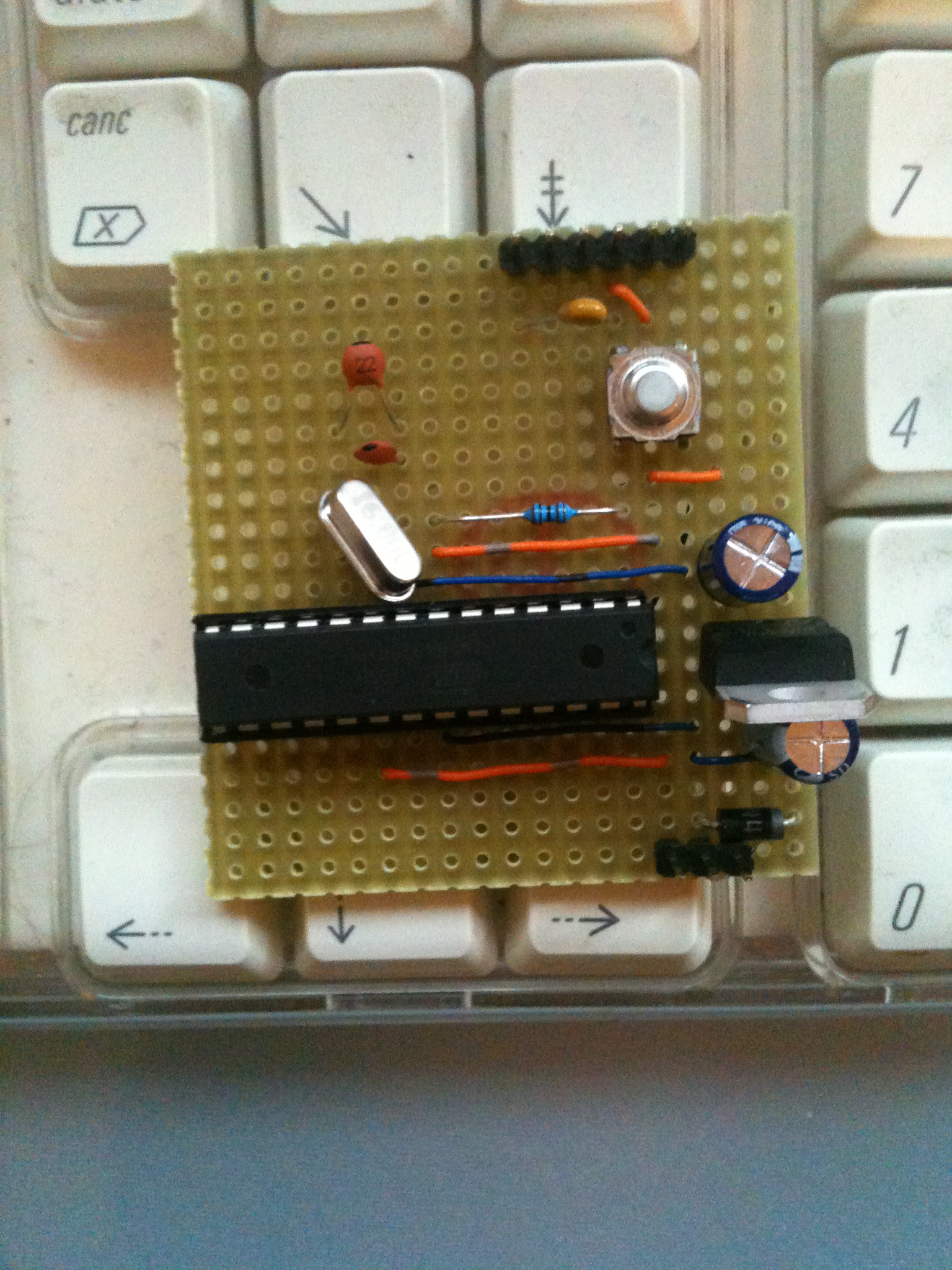
Finally the first release of "gigino", our low cost Arduino prototyping board, is out.
Gigino is based on an ATMEGA328P-PU microcontroller produced by ATMEL.
Really it isn't a mounted board, it is a kit.
So you can take the components and then you can mount them as you want.
Anyway we'll provide two schemas that work fine.
The BOM (Bill of Materials)
| Id | Quantity | Item | Description |
| 1 | 1 | Veroboard | 19×20 holes |
| 2 | 1 | ATMEGA328P-PU | with Optiboot preloaded |
| 3 | 1 | 28-pin DIL socket | |
| 4 | 1 | L7805CV | Linear voltage regulator 5V/1A |
| 5 | 1 | Q 16,0 MHz U-4/6B | Crystal Low Profile |
| 6 | 2 | 100uF/35V SC 25V electrolytic capacitors | |
| 7 | 2 | 0,22pF Y5V RM2,5 50V Capacitor | Ceramic Capacitor Leaded Multilayer |
| 8 | 1 | 1N4007 Rectifier diode 1A/1000V DO41 | |
| 9 | 1 | Push-button into PCB micro | 4×3 holes |
| 10 | 1 | RMM 1% 10 K Resistor | Metal Film Resistor 0204 0,4W |
| 11 | 1 | 14 pin male header | |
| 12 | 1 | 0,1uF Y5V RM2,5 50V Capacitor | Ceramic Capacitor Leaded Multilayer |
| 13 | 2 | Some hookup wire | 2 colors are better |
The clean schema
We are providing the following clean schematic (clean because we are using one component per raw), but we will publish another schematic to gain some raws so to have more space for your own additional functions.
The kit
FTDI connector pinout:
0 – GND
1 – UNUSED
2 – VCC (5v)
3 – Tx
4 – Rx
5 – DTR
The development tool
To develop software for this board you can use the standard tools for Arduino. Simply go to www.arduino.cc and download the Arduino IDE. We are going to publish a Linux distro, bootable from a USB key, specialized for prototyping. So keep in touch.
Connecting to your PC
The gigino board can be connected to your PC or to other devices trough the serial line. The serial line provided by gigino is a ttl (5v) one, so you cannot connect directly the PC to gigino, instead you should use a USB to rs232ttl adapter (look at FTDI cables) or, if you have a serial port on your PC, you can use a RS232 to TTL adapter like this.
Power connections
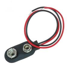
You can connect power to the VIN and ground, 8 to 12VDC are good values. We are using a standard 9V battery with an adapter cable. 

If you are planning to use a 12V power supply adapter you should also use a heatsink on the 7805, if you are planning to use a power supply adapter with more than 12 volts you should add a 7812 voltage regulator before the 7805.
If you use a FTDI cable to talk with gigino then you can avoid the use of external power since gigino can be powerd via the USB power lines, but make sure that external power (VIN) isn't connected at the same time.
Programming gigino
Loading a sketch can be done by connecting a 5V FTDI board or cable to the 6 pin header or by temporarily transferring the ATmega chip into another Arduino for programming. You can also use our RS232 to ttl adapter, but in this case you shall execute the following steps:
- press and hold the reset button
- press the upload button in the IDE
- release the reset button
I/O Lines
Gigino uses the same naming convention of the Arduino UNO board (in the scheme you'll find where to take the pins)
- Each of the 14 digital pins on the Uno can be used as an input or output, using pinMode(), digitalWrite(), and digitalRead() functions. They operate at 5 volts. Each pin can provide or receive a maximum of 40 mA and has an internal pull-up resistor (disconnected by default) of 20-50 kOhms. In addition, some pins have specialized functions:
- Serial: 0 (RX) and 1 (TX). Used to receive (RX) and transmit (TX) TTL serial data. These pins are connected to the corresponding pins of the ATmega8U2 USB-to-TTL Serial chip.
- External Interrupts: 2 and 3. These pins can be configured to trigger an interrupt on a low value, a rising or falling edge, or a change in value. See the attachInterrupt() function for details.
- PWM: 3, 5, 6, 9, 10, and 11. Provide 8-bit PWM output with the analogWrite() function.
- SPI: 10 (SS), 11 (MOSI), 12 (MISO), 13 (SCK). These pins support SPI communication using the SPI library.
- LED: 13. There is a built-in LED connected to digital pin 13. When the pin is HIGH value, the LED is on, when the pin is LOW, it's off.
- The Uno has 6 analog inputs, labeled A0 through A5, each of which provide 10 bits of resolution (i.e. 1024 different values). By default they measure from ground to 5 volts, though is it possible to change the upper end of their range using the AREF pin and the analogReference() function. Additionally, some pins have specialized functionality:
- TWI: A4 or SDA pin and A5 or SCL pin. Support TWI communication using the Wire library.
- There are a couple of other pins on the board:
- AREF. Reference voltage for the analog inputs. Used with analogReference().
- Reset. Bring this line LOW to reset the microcontroller. Typically used to add a reset button to shields which block the one on the board.
- See also the mapping between Arduino pins and ATmega328 ports. The mapping for the Atmega8, 168, and 328 is identical.


Hi,
In your BOM – Bill Of Materials, there are 100uF/35V SC 25V electrolytic capacitors . But in your drawing it say 1uf. So which one i need to use.Actually i'm doing this gigino as my project.
thank.
You are right!
Now I don’t have the prototype with me, anyway 10uF to 100 uF should be good.
In any case take a look at the datasheet of your 7805.
Thanks Admin.
Actually i don't know how to read datasheet. Just copy and solder 🙂
Hi, for capacitor, it is 22nF or 22uF. list and image are different.
Tq.
The BOM is correct..
22pF